Friday, January 7, 2011

A Graphics Programmer's Toolbox, part 2 (Matrices and Coordinate Systems)

The second round of "what's in your mathematical toolbox".

If you missed the previous part, consider part 1 first.

Coordinate Systems

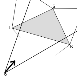
A vector (u, v, w) can be expressed as ui + vj + wk, which is the representation of the vector in the standard coordinate system. We can define other coordinate systems with different basis vectors. For example, if we take a mirrored coordinate system in which the basis vectors are -i, -j and -k, then the point whose coordinates in that system are (-u, -v, -w) matches the same point:

(-u)(-i) + (-v)(-j) + (-w)(-k) = ui + vj + wk.


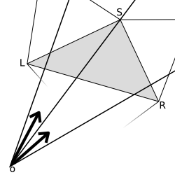
Co-ordinates of a point in a system are simply the multipliers of the basis vectors: if the basis vectors are i', j' and k' and the coordinates are (u, v, w), then, if the the coordinate system's origin is at zero, the point matching those coordinates is ui' + vj' + wk'. If the coordinate system's origin is not at zero, we have to take that into account. In that case, if the origin is at p, the point becomes ui' + vj' + wk' + p.


Now if the vectors p, i', j' and k' are known in the standard basis, we can calculate the coordinates of the point in the standard coordinate system:

(u i'.x + v j'.x + w k'.x + p.x,
u i'.y + v j'.y + w k'.y + p.y,
u i'.z + v j'.z + w k'.z + p.z),

or simply
u i' + v j' + w k' + p.


Often the basis vectors i', j' and k' are of unit-length and orthogonal to each other. The mathematical notation for this is |i'| = 1, |j'| = 1, |k'| = 1 and i'·j' = 0, j'·k' = 0 and k'·i' = 0, where · is the dot product. If all these hold, the coordinate system is called orthonormal. If the basis vectors are only orthogonal but not necessarily normalized, then the coordinate system is called just orthogonal.


Matrices

A matrix is simply an array of numbers. Another fancy term here. That's all.


Matrix notation

There are different sizes of arrays matrices of course, although the 3x3 and 4x4 arrays matrices are the most useful in 3d graphics. Like in many programming languages, the first number is the height number of horizontal lines rows, and the last number is the width number of vertical lines columns. An example for a 3x4 array matrix in C would be float matrix[3][4].

Like vectors, arrays matrices can be summed. It's just the componentwise sum. The difference of matrices is the same componentwise difference as for vectors. Like vectors, you can multply and divide them by numbers scalars. There's also the Hadamard product (componentwise product), but that's not so common. Like for vectors, the most useful array matrix multiplications are something different. I'll come back to that later.

Elements of an array a matrix are usually denoted by subscript notation; first the row and then the column:

[A1,1 A1,2 A1,3 A1,4]
A = [A2,1 A2,2 A2,3 A2,4]
[A3,1 A3,2 A3,3 A3,4]

For example, if

[11 12]
A = [21 22]
[31 32],

then A1,2 = 12, A2,1 = 21 and A3,2 = 32.


Matrices and Coordinate Systems

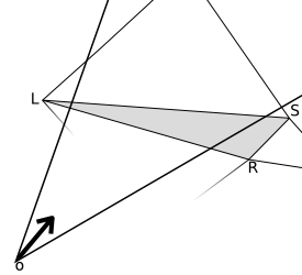
Let's go back to the coordinate systems and take one whose origin is at zero and whose basis vectors are i', j' and k', not necessarily orthogonal nor unit-length. Let's store these vectors as a 3x3 matrix:

[i'.x j'.x k'.x]
M = [i'.y j'.y k'.y].
[i'.z j'.z k'.z]

This matrix is often called the base of the coordinate system since it contains the basis vectors. Next, let's make the vector (u, v, w) a matrix too:

[u]
(u, v, w) = [v].
[w]

Let's call that previous point (u, v, w) with the name p and let's suppose that these coordinates are given with respect to the previously given base. To get the coordinates of p in the standard coordinate system, we need to know the vectors i', j' and k' in the standard coordinate system. If we do, we have

(u i'.x + v j'.x + w k'.x,
p = ui' + vj' + wk' = u i'.y + v j'.y + w k'.y,
u i'.z + v j'.z + w k'.z).

According to the previously introduced scheme, let's make this vector a matrix too:

[u i'.x + v j'.x + w k'.x]
p = [u i'.y + v j'.y + w k'.y].
[u i'.z + v j'.z + w k'.z]

After all, vectors are matrices too. Now let's introduce the matrix product for a 3x3 array matrix and a 3-vector 3x1 matrix (which is often called a column vector):

[i'.x j'.x k'.x] [u] [u i'.x + v j'.x + w k'.x]
[i'.y j'.y k'.y] * [v] = [u i'.y + v j'.y + w k'.y]
[i'.z j'.z k'.z] [w] [u i'.z + v j'.z + w k'.z]

[i'.x] [j'.x] [k'.x]
= u [i'.y] + v [j'.y] + w [k'.y] = ui' + vj' + wk'.
[i'.z] [j'.z] [k'.z]

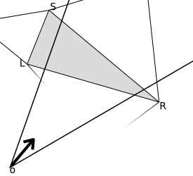
In other words, matrix * vector transforms the vector from another coordinate system to the standard coordinate system.


Matrix Times a Matrix

Well then, how about matrix * matrix? It's simple. Really, just multiply with the columns of the second matrix one by one and collect the results. Denoting the columns of the second matrix as a1, a2 and a3 and the first matrix as M, we have

[i'.x j'.x k'.x] [a1.x a2.x a3.x]
M = [i'.y j'.y k'.y], A = [a1 a2 a3] = [a1.y a2.y a3.y].
[i'.z j'.z k'.z] [a1.z a2.z a3.z]

Now then, the multiplication is done to the column vectors one by one and collected:

M * [a1 a2 a3] = [M a1 M a2 M a3].

The column vectors of the result matrix are, like we had it before, just the three vectors transformed one by one. The result is a 3x3 matrix

[(M a1).x (M a2).x (M a3).x]
[(M a1).y (M a2).y (M a3).y].
[(M a1).z (M a2).z (M a3).z]


Now we're able to transform points to the standard coordinate system by matrix multiplication. But how about the inverse? Surprisingly, that's done by multiplying by the inverse matrix; more about that later.

That's all, folks!

The Future ...
Please ask for details in the comments. The next topic might be 4x4 matrices, homogenous coordinates and coordinate systems whose origin is not at zero. Probably also discussing matrix transpose and inverse. Please comment and request for a topic if you want.

You might want to read more about matrix multiplication or coordinate systems. ;)

Tuesday, December 21, 2010

A Graphics Programmer's Toolbox, part 1 (Vectors)

Everyone needs to know the basic tools of their art. I thought I'd like to share with you my equivalents of a screwdriver, a hammer and maybe a saw, some of the everyday tools of a graphics programmer.

Vectors

A vector is just a fancy word for a point in space. So in 2d, a vector is just a co-ordinate pair (x, y). In 3d it's (x, y, z) and in 4d it's (x, y, z, w). A mental image of four dimensions is not important here - don't even try.

Some vectors are given a special name. The vector in the middle of the space, the zero-vector, is called the origin. In 3d, that's (0, 0, 0). The vector to the right, (1, 0, 0), is called i. The up-vector, (0, 1, 0) is j. The remaining vector, (0, 0, 1), is named k and it's the backwards-vector.

Sum, Difference and Multiplication

These points, or vectors, can be added and subtracted. Adding a vector to another is just summing the coordinates of the vectors; if a = (X, Y) and b = (x, y), then a + b = (X+x, Y+y). Subtracting is done in a similar way, a - b = (X-x, Y-y). Multi-dimensional calculation is not really that much more complicated. It's basically just the same, but doing the operations to all co-ordinates, instead of just one.

Sum and difference are easy, but with multiple components (co-ordinates) there are many kind of vectors multiplications with different meanings. Complicated? I didn't say anything; not yet.

Multiplying by a scalar just multiplies the distance of the point with respect to the origin. This scalar is just a fancy name for a real number; you might have noticed mathematicians love fancy words. So in other words, if a = (x, y, z) and r is a real number, then a*r = (x*r, y*r, z*r). If r is negative, you can see that the point will also be mirrored with respect to the origin.

The componentwise product works the same way as sum and addition, but it's a bit rarer in the mathematical context. It's very useful in computer graphics though, mostly in lighting calculations. This product is denoted with , and if a = (R, G, B, A) and b = (r, g, b, a), then ab = (R*r, G*g, B*b, A*a). Mathematicians call this product the Hadamard product (Jacques Hadamard, 1865 to 1963). Componentwise product is fine too.

There are also at least two more very useful products.

Dot and Cross Product

The dot product is the screwdriver of the toolbox. This product is written with the symbol •, and it's the sum of the components' products; if a = (X, Y, Z) and b = (x, y, z), then ab = X*x + Y*y + Z*z. Notice that the result is a scalar, or a real number. The usefulness of this product comes mainly from the fact that if a and b are both unit-length (X2 + Y2 + Z2 = 12), then, denoting the angle between b and a with α, it holds that ab = cos α. Generally, if a and b are not necessarily of unit length, then ab / |a||b| = cos α, where |v| denotes the length of a vector.

In 3d there's the cross product. Its main purpose is outputting a vector that's orthogonal to two given vectors, i.e. getting their normal vector. It can also be used to calculate the sine of the angle between two vectors. A funny fact is that a cross product only exists in 3 and 7 dimensions. The formula for cross product is pretty symmetric; if a = (X, Y, Z) and b = (x, y, z), then a × b = (Yz - Zy, Zx - Xz, Xy - Yx). Notice that this product is a bit special in that a × b = - b × a, so you can't just switch the order mindlessly. It is also true, like stated before, that a × b is orthogonal to both a and b. In mathematical notation, (a × b) • a = 0 and (a × b) • b = 0. For the direction of the cross product vector there's the right-hand rule, well described in this wiki article.

Continuing soon...
It's a known fact that once you open a Wikipedia page, you just can't stop reading. I'll set here a trap for you and I bet you can't oppose it:
Euclidean vector
Unit vector
The Gram-Schmidt algorithm

I'm planning to continue with matrices, bases, coordinate transforms, quaternions and such. If you'd like to suggest a topic or ask a question, please comment! :)

Thursday, November 18, 2010

Beamcasting

I am Topi "Sharph" Talvitie, the other coder in the Umbrella Project. I've been mostly helping with path finding related algorithms in the project.

Efficient path finding algorithms run on a graph of links between vertices. These graphs are a bit large to be distributed as precalculated data, so they need to be generated at runtime. If possible, this process should be fast enough to be unnoticeable. Our solution to the problem is casting a beam from each vertex to find the vertices that this vertex is linked to.

In the figure below there is a beam (the red area) cast from vertex A of polygon P. The vertices seen from vertex A are circled.


If we are able to query the whole visible polygon from any point, we can use the same algorithm for many interesting effects too, such as checking if the player is seen by a character in the game. Thus we need an algorithm that can cast a beam from both polygon vertices and free space.


So how to do this efficiently? After considering some grid accelerated algorithms that turned out to be quite complex, we realized that a triangle tessellation (triangulation) of the map would be very useful.


We will shortly describe the algorithm. There's still a cake for you in the action phase after that.

Initiating the Cast


Because the polygon map is tessellated, the starting point of the beam O (lower right) is an interior point of exactly one triangle T. We divide the beam (lower left) into at most three smaller beams (lower right: A, B and C) by splitting it by the sectors to the triangle edges.

Each of these smaller beams sees exactly one edge of the triangle T. If that edge is a wall of a polygon, just add it. For the unblocked beams, we advance to the next neighboring triangle. (N1 for A, N3 for B, N2 for C)


The case of starting from a vertex is very similar.

Recursion


In the recursion step we consider a smaller beam, recursed to a triangle (the lower triangle in the figures below). Due to splitting the beam when entering new triangles, the beam will enter the neighboring triangle (gray) through exactly one edge (L-R).

We take the line to the opposite vertex of this new triangle (lower right, O-S) and use this line to deduce which neighbors of the current triangle (gray) will need to be recursed into. If both edges (L-S, S-R) are seen, both neighboring triangles will need to be analyzed (lower right).


If only the leftmost edge is seen, only the left triangle will need to be analyzed (lower left). If only the rightmost edge is seen, only the right triangle will need to be analyzed.


Again, if the triangle we are advancing into is part of an obstacle polygon, just add the edge. And finally, to keep the result polygon correctly ordered, the search should be done depth-first and always to the same direction first.

There exist many good libraries for triangulation. We used poly2tri, licensed under the New BSD License.

Something to think...


It is proven that in pathfinding, links from vertex A to vertices in beam C are not needed. Can you figure out why? Might be confusing at first!


And at last...

Action!


We prepared a scene for your investigation for this very realistic simulation of a
crime-in-action, a western style bank robbery. The blue casting star represents the sheriff and the red casting robber represents the bad guy. Enjoy!


(Written by Topi Talvitie, edited by Markus Kettunen)

Monday, October 18, 2010

2010-10-18. A Game Engine from Scratch

After modifying the collision detection algorithm to suit a vector map, and fixing some very nontrivial floating point problems I decided that it might be time to take a step towards the level editor. Back then I had no nice means for more advanced interaction with the user, so my next step was to make a widget system.

While playing with Google's V8 engine, which I later abandoned, I had become familiar with Javascript and its event system. I found it quite nice so I decided to take its design as a base for designing my own system. It appeared to be a rather good plan.

Here is the debugging view I used at this point.


On the left lower corner you can see some widgets, one of them showing the mouse position and the other being an automatic FPS calculator. Whoa!

The small squares in the ground show the space division that is used to accelerate collision detection. Collision detection against the walls only needs to be done when the player is inside one of those bluish rectangles, and only the walls going through the same rectangle need to be checked against. In real use, though, the rectangles should be a lot larger.

Another noteworthy object in the picture is that steamtank. Alas, this time without all that eye candy. When the time is right I will have finished generalizing the rendering engine for arbitrary scenes, also supporting a large variety of options to make the game playable on a bit older computers too. This is something that I'm doing with ubershaders, though more on them later.

Currently I'm writing a more user friendly exporter for Milkshape 3d for our model and animation formats. Why not use an existing format? That's an interesting question with an even more interesting answer. I have also been rewriting the animation system to better support animation changes. But all this will be ready soon enough, and there will be so many interesting things to discuss.

It surely isn't a small job to make a complete game engine from scratch, but it's so much fun!

Sunday, September 12, 2010

2010-09-12. Path finding

After abandoning V8 I wrote some code for collision detection. The plan was that our maps would be made of squares, and inside those squares we would have a grid for more precise collisions. I also wanted that the player would slide along the walls instead of getting stuck, so I needed to do some raycasting. The resulting collision map would be too large to keep in memory, so I ended up writing a system for raycasting edges that were created in real-time...

At this point another competent coder joined the team and we were discussing path finding algorithms for the game. He made a quick A* implementation for testing, and it was soon apparent that the desired grid size was far too large.

After thinking of this for a while we deduced that our lives would be much easier if we changed the maps into vector maps and forgot about the tiles. It also made my life easier. This one was a really good decision!

One of the problems we had with the new polygon-based path finding algorithm was that the precalculation time required for fast path finding would be all too large. We needed to search all the visible polygon corners from all the other polygon corners in the map. Each one of these would require checking all the other polygons. This was unacceptable. Moving from a map to map had to be fast.

Even after heavily optimizing visibility tests: raycasting with grid-based acceleration and limited polygon density, it would still be at least O(n2). For fast precalculation times we really didn't have the time to find all the visible corners. We needed a local approximation, caring only of the nearest polygons. We achieved this by limiting the visibility range and adding 'dummy points' where there were no polygon corners nearby, to connect to the far-away polygons. The resulting precalculation time was unbelievably fast and the actual path-finding part didn't suffer much.


Here's an image of the precalculation process. The green grid represents the grid used in the acceleration. It should be a lot sparser in a real use case. The blue polygons represent the actual walls used in the path finding, pulled out from the red original walls next to them. The resulting, somewhat optimized network of links, is drawn in red.

This local system requires the found route to be cleaned afterwards, by dropping any possible unnecessary waypoints. But there's also a bug in the image. Can you spot it? Can you be sure? :-)

Monday, July 26, 2010

2010-07-26. Scripting with V8

Map scripting

After a long break in writing here I'm back again, and the project has taken some nice steps forward. We have been researching useful scripting languages for map scripting. This process isn't what I'm most interested in, nor does it produce cool images, so I haven't been too motivated to write about it before. I will now, shortly.

To implement complex behaviour in maps we need to use some scripting language. Common scripting languages include Javascript, Lua and Python, among others. These all have been good candidates for us.

At first I took a look at embedding Python into a C++ program. Python's micromanagement of resources, like manually incrementing and decrementing reference counters, looked shuddering. It's also a rather slow language, typical efficiency (compared to C) being around 1/200th.

I had also heard horror stories about people needing ridiculous optimizations in their Lua scripts to get even decent speed. On the other hand, Google's Chrome is one of the fastest web browsers out there when it comes to Javascript. And Google's Javascript engine, V8, is out there for free. And it natively supports C++ too. Javascript by itself isn't a dirty language either. Sounds like a dream, no?

I took some time to experiment with it. I wrote wrappers to understand it better, experimented with it, made test APIs and tools and other small libraries for it. It worked somewhat, but I ended up rewriting stuff too many times, trying to find a clean general solution for my needs.

There wasn't too much documentation for the new V8 library yet so I ended up having lots of trouble and frustration with it. I had gotten it to work, even in a way that would be useful for a small project, but I couldn't get it clean enough to use in a large game, without the frustration of having to cope with dirty code.

On top of that, when trying to compile Sad Umbrella for Arch Linux, it then appeared that the V8 release didn't even compile; it had constructs in the source code that weren't supported by the newest GCC version. Maybe they have fixed it by now, maybe not, but that wasn't the only Linux distribution having problems with V8. Many other people reported difficulties getting V8 from their Linux distribution's repositories, and it would be almost impossible to get V8 for a handheld device. If we ever decided to port the game for one.

I feel the library is still too immature for actual use by 3rd parties.

Wednesday, May 19, 2010

2010-05-19. Music for the Umbrella Project

Coining the term 'idea music'

I am Pauli "Gwaur" Marttinen. I am the appointed composer for the Umbrella Project, though one other composer has also been invited to fill some of the stylistic gaps that I don't span. I specialize in music in the symphonic or otherwise classical sense. I am far for being a pro, but I'm aiming for professional studies in percussion and/or conducting.


At this point of the Umbrella Project, virtually no game exists. There's an incomplete graphics engine, the game and scripting engines are just being conceived, and the plot setting is only starting to get out of the "vague idea" state. This is the opposite of an ideal phase for making the score: I have no idea what I am making music for.

I have practically no mental image of where the project is headed to. There's too little concept art, 3D models, scripts or storyboards to follow. It is hard to get any inspiration that's directly linked to this game. If I make a piece of music for the game at this point, who knows if it will it be used in a cutscene or a playable place, or in the closing credits? Should I make it repeatable? Should I make other versions of it, for different situations?

It is of course never a bad idea to store ideas beforehand. Even if a piece I go ahead and finish now will ultimately be unused, ideas can be recycled. Maybe a new piece with a new structure but some same themes. Or the same structure and new themes in the same style. On the other hand, changing things may be difficult if, for instance, some pieces have music played with real instruments instead of computerized ones.

Something like this has been done at Studio Ghibli, a film studio that produces some of the most popular animated features. If you look for soundtracks of Ghibli's films, you might come across some albums subtitled "Image Album". These are albums of music inspired by storyboards and concept art, composed by the composer in the earliest phases of filmmaking, as opposed to music often being one of the last things to be made. With this, the composer has more time to fine-tune the music, discard some and make some new, according to the project leader's wish.

In our case, we are currently trying out something I might call "idea music" instead of image music, since we have no images yet. What happens right now is that the project coordinator asks me to make "something based on this idea". I try to follow that idea, make something, and suggest whatever I come up with. By now we have three pieces of music, but none of us knows exactly where and how to use them.

Things are starting out slow, and there are several reasons for it. None of us are professionals, and we have little experience on working on such an ambitious project. We live quite far away from each other, so we are relayed through the Internet and seldom meet in real life, but the Internet doesn't always do it for you. Also, frankly, my personal video game interests don't match with this one. ;)